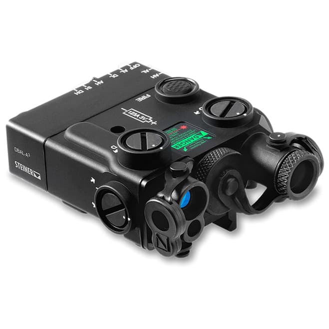
Steiner DBAL-A3
Civilian IR/visible laser aiming device
- Price
- $1,725
- Weight
- 8 oz
- Brand
- Steiner
- Category
- Lasers
Featured in
Features
- •IR laser
- •IR illuminator
- •Green visible laser
Capability Boosts
Recommended For
+14 more
Where to Buy
Compare current prices and availability from retailers we work with.
Steiner DBAL-A3 Green Laser Devices w/ IR Pointer and IR Illuminator, Black, 9008
Dbal-A3 Civilian Dual Beam Visible And Ir Aiming Laser - Dbal-A3 Green Aiming Laser, Black
Price History
90-day low $1619.99More lasers guides & articles
Guides


Overview
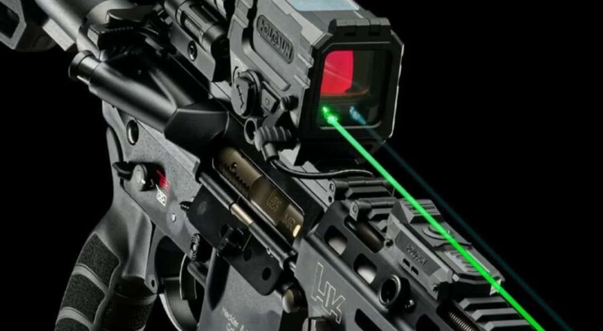
The Steiner DBAL-A3 combines an eye-safe IR laser pointer, IR illuminator, and green visible laser in a compact civilian-legal unit. Steiner's warning label rates all three emitters Class IIIa: the infrared pointer at 0.7mW, the infrared illuminator under 4mW, and the green visible laser under 5mW. The co-aligned visible and IR lasers make zeroing procedures straightforward; dial in the green laser during daylight, and the IR is automatically zeroed for night vision operations.
Built from lightweight aircraft aluminum with a rugged black finish, the DBAL-A3 is listed at 8 ounces and is rated submersible to 5 meters. The IR illuminator's adjustable beam divergence covers a usable flood-to-spot range for different engagement distances and tactical scenarios. Being laser-based rather than LED, the illuminator produces minimal downrange signature compared to traditional LED IR illuminators, enhancing covert operation capability.
The DBAL-A3 runs off a single CR123 battery with approximately 3 hours runtime using both IR illuminator and laser simultaneously. While the civilian eye-safe IR output is lower than military full-power units, the DBAL-A3 provides a practical top-rail laser and illuminator workflow for most civilian and law enforcement night-vision applications.
Key Features
- Triple laser system: Class IIIa IR pointer (0.7mW), Class IIIa IR illuminator (<4mW), Class IIIa green visible (<5mW)
- Co-aligned visible and IR lasers simplify zeroing procedures
- Adjustable IR illuminator for spot-to-flood tuning
- Laser-based IR illuminator minimizes downrange signature vs LED
- Aircraft aluminum housing rated submersible to 5m
- 3-hour runtime on single CR123 with dual IR laser/illuminator use
Pros
- +First civilian-legal eye-safe IR laser/illuminator combo unit
- +Co-aligned lasers eliminate separate zeroing procedures
- +Laser-based illuminator more covert than LED alternatives
- +Civilian version of proven military hardware
- +Compact 8 oz class form factor
- +Cold weather operation capability
Cons
- −Eye-safe IR illuminator less powerful than military full-power units
- −Effective range limited to ~200 meters vs LED illuminators
- −Premium pricing for civilian eye-safe configuration
- −IR illuminator dimmer than dedicated LED IR lights
- −ITAR restricted (no international shipping)
Setup & Operation
Step-by-step procedures for setting up, operating, and maintaining the Steiner DBAL-A3.
- → Install the Battery
- → Mount the DBAL-A3 with the Quick Release Mount
- → Read the Activation and Mode Selector Switch
- → Activate the Laser and Latch Continuous On
- → Use the Two Remote Cable Ports and the Visible Override
- → Focus the IR Illuminator from Spot to Flood
- → Return the Adjusters to the Factory Neutral Preset
- → Apply a Positive Load on Every Counter-Clockwise Adjustment
- → Zero the Aiming Laser on a 25-Meter Range
- → Understand the Blue Safety Screw
- → Clean and Inspect the DBAL-A3
Install the Battery
The DBAL-A3 takes a single 3 V CR123A. Steiner notes that losing or removing the O-ring from the battery cap will let water into the housing, so the O-ring check is not optional on a device rated for submersion.
The green LED on the rear housing, between the activation and mode selector switch and the visible override port, doubles as the low-battery indicator. Solid green means the laser is emitting. If it starts to blink, the cell is low and the manual says to replace it immediately rather than finish the session on it.
- • One 3 V CR123A battery
- • Silicone grease for the O-ring
- • Soft cloth or disposable applicator
- 01
Clear the weapon
Be sure the weapon is CLEAR and on SAFE before proceeding, and confirm the activation mode selector switch is at OFF.
- 02
Unscrew the battery cap counter-clockwise
Turn the battery cap in a CCW direction, then remove and properly discard the spent cell.
- 03
Inspect the compartment and cap
Check the battery compartment for dirt, moisture, and corrosion and clean it with a soft cloth or disposable applicator. Inspect the cap threads and contacts at the same time.
- 04
Inspect and grease the O-ring
Check the O-ring seal on the battery cap for sand and dirt particles and for nicks, cuts, or drying. Lubricate it with a thin film of silicone grease using your fingertips, and never lift an O-ring out with a sharp or metal object.
- 05
Install the cell and hand tighten
Install the battery as indicated by the marking on the DBAL-A3 housing, then reinstall the battery cap and hand tighten it in a CW direction.
Do not store the DBAL-A3 with the battery installed. Steiner repeats this warning in four separate places in the manual, and operator maintenance is explicitly defined as installing the cell before a session and removing it after.
Mount the DBAL-A3 with the Quick Release Mount
The integrated quick release mount is a lever, a rail buffer, and a crossbar, and it goes on top, left, or right rail. Rail position matters more than it does on most lasers: if the DBAL-A3 comes off, it has to go back in the same slot or the zero goes with it, and the mounting configuration changes which adjuster does what.
Steiner names the two failure modes directly. Failing to fully tighten the quick release mount causes zero retention problems, and the base of the mount has to sit fully seated on the rail with no front or rear overhang.
- 01
Clear the weapon
Confirm the weapon is CLEAR and on SAFE before mounting.
- 02
Open the lever perpendicular to the housing
Open the quick release mount so that the lever sits perpendicular to the DBAL-A3 housing.
- 03
Buffer the left side and index the crossbar
Place the rail buffer against the left side of the MIL-STD-1913 rail and align the crossbar on the bottom of the mount with a rail slot.
- 04
Push forward and close the lever
Push forward on the DBAL-A3 so the crossbar contacts the front of the rail slot, then move the quick release lever until it is parallel with the body of the laser housing.
- 05
Leave room for the battery and check the offset
Place the device far enough back on the rail to allow battery replacement without removing it from the weapon. With the adjusters at factory neutral, the visible or IR point should project on the same side of the target as the laser is mounted and fall within 10.2 cm of the bore at 25 meters.
Note which rail slot you zeroed in before you take the laser off. If the unit will not stay tight on the rail, Steiner's own troubleshooting sequence is to move it to a different position on the rail, then a different rail, then replace the rail.
Read the Activation and Mode Selector Switch
The rotary switch on the left rear of the housing sets both which emitter fires and at what power. Reading through the positions, the visible side carries AH and AL, then OFF, then the infrared side carries AL, DL, AH, IH, and DH. The switch is a rotary detent, and Steiner warns that the DBAL-A3 will not operate if the switch is not precisely aligned with a marked position, which is a real failure mode in cold weather when the detent stiffens.
Steiner also assigns each position a job, and one of those assignments is a rule rather than a suggestion: do not zero on the high-power visible setting.
- 01
AH, visible high
High-power visible pointer. The manual's use case is pointing or aiming at close range in daylight, or at longer range in low light. Steiner explicitly says do not use this position for zeroing the weapon.
- 02
AL, visible low
Low-power visible pointer. This is the position the manual designates for zeroing the laser to the weapon in low light conditions.
- 03
OFF
The DBAL-A3 will not operate. This is also the position the manual requires before inspecting the exit port lenses, because the fire button and remote pad will otherwise fire a laser you are looking into.
- 04
AL and AH, infrared pointer
Low and high power IR pointer. AL is for pointing, zeroing, and training in low or no light. AH is for pointing at long distances in low or no light.
- 05
IH, infrared illuminator high
High-power IR illuminator alone, for supplemental illumination of shadowed areas.
- 06
DL and DH, dual infrared
IR pointer and illuminator together at low and high power. DL is for pointing and aiming indoors and outdoors at close range plus supplemental illumination. DH covers long-distance pointing with illumination at the same time.
The manual's system description calls the DBAL-A3 a Class IIIb laser device, and its warning label and safety data table give the emitter ratings as under 5 mW Class IIIa for the visible pointer at a 154 m nominal ocular hazard distance, 0.7 mW Class IIIa for the IR pointer at 114 m, and under 4 mW Class IIIa for the IR illuminator at 114 m. Do not stare into the laser beam, do not look into it through binoculars or telescopes, do not point it at mirror-like surfaces, and do not shine it into anyone's eyes.
Activate the Laser and Latch Continuous On
The integrated momentary activation switch sits on top of the housing to the left of the word FIRE, and the remote cable pad behaves identically. Press and hold for momentary. Press twice in rapid succession for a five-minute continuous on. Press once more to drop back to momentary.
Steiner includes a detail worth knowing for anything done quietly: the click sound of the integrated switch is minimized by pressing the center of the switch rather than an edge.
- 01
Select a mode first
Rotate the activation mode selector switch to the position you want. The fire button does nothing at OFF, and the device will not operate if the rotary switch sits between detents.
- 02
Momentary
Firmly press and hold the integrated momentary activation switch. The selected laser function runs while the switch is held and turns off when you release it.
- 03
Continuous on
Press the switch twice in rapid succession. The DBAL-A3 latches on for five minutes. Press once more to return the unit to momentary activation.
- 04
Read the green LED
The green LED lights while the laser is emitting and stays lit through a five-minute continuous run. A blinking LED is the low-battery indicator, not a laser status.
Use the Two Remote Cable Ports and the Visible Override
The DBAL-A3 has two remote cable ports, and they do different things. The right-hand port is for standard operation: a pad plugged in there always fires whatever the mode selector has selected. The left-hand port is marked Visible Override and fires only the visible pointer, regardless of the infrared mode the switch is on.
The override follows the power level rather than the emitter. If the mode selector is on any high-power infrared position, the override fires the visible laser on high; on any low-power infrared position, it fires the visible laser on low. The same port takes the supplied Y-cable, which drives a Steiner OV-2 or FML tactical light and the visible laser from one pad.
- 01
Pick the right port for the job
Use the right-hand remote cable port for all standard laser operation. Use the left-hand Visible Override port only when you want a pad that fires the visible pointer over the selected infrared mode.
- 02
Seat the plug with a gentle twist
Gently twist the plug into the remote cable port. The plug locks in place automatically once seated.
- 03
Secure the pad with the loop fastener
Use the supplied tape fastener loop to secure the remote cable switch to the weapon in a position your support hand reaches naturally.
- 04
Verify the mode selector is on a laser setting
Neither port does anything with the activation mode selector switch at OFF. Rotate it to a laser setting, then press the pad and confirm the green LED lights.
- 05
Remove by pulling the plug sleeve back
To remove a remote cable switch, pull back on the plug's sleeve. Never remove it by pulling on the cable; Steiner lists that as a specific caution.
Focus the IR Illuminator from Spot to Flood
The illuminator focus knob carries a white dot that indexes against a matching dot on the laser assembly chassis, and the housing is marked with the rotation direction for spot and flood. Divergence runs from roughly 95 mrad at the focused point out to 250 mrad wide open.
There is a sequence to finding the true focus point, and it is not simply turning the knob until the beam looks tight. Run it to the mechanical stop first, then come back to the dots.
- 01
Open the exit port cover first
Open the IR POINT/ILLUM exit port cover before turning the focus knob. Steiner warns that turning the knob with the cover closed damages the cover.
- 02
Run the knob counter-clockwise to the stop
From the shooter's perspective, turn the illuminator focus knob CCW fully toward spot until it reaches the mechanical stop.
- 03
Index on the white dots
Turn the knob CW until the white dot on the focus knob lines up with the white dot on the chassis of the laser assembly. This is the focus point, the smallest diameter beam the illuminator produces.
- 04
Open toward flood as the target requires
Rotate the focus knob CW from the focus point to widen the beam. Match the beam size to the range and the size of the area you need lit rather than running it wide by default.
Before water operations or immersion, turn the illuminator focus knob CCW to its stop. That fully compresses the internal O-rings and is what keeps water out of the housing. Do not force the focus knob past its normal end of travel in either direction, and expect more resistance in extreme cold.
Return the Adjusters to the Factory Neutral Preset
The DBAL-A3 leaves the factory with the beam parallel to the bore. Going back to that preset is the starting point for every zero and the fix any time the click value has gone soft at the ends of travel.
Always start with the adjuster marked U/D. Each adjuster and each adjuster guard carries a white dot, and the alignment of the two is the neutral index.
- 01
Turn the U/D adjuster clockwise to the natural stop
Rotate the adjuster marked U/D CW until it reaches the natural stop. Do not force it past the mechanical stop.
- 02
Back it off one and one-quarter turns
Turn the same adjuster CCW one and one-quarter turns.
- 03
Index on the white dots
Turn it CW until the white dot on the adjuster aligns with the white dot on the adjuster guard.
- 04
Repeat on the R/L adjuster
Run the identical sequence on the adjuster marked R/L: CW to the natural stop, CCW one and one-quarter turns, then CW until the dots align.
The visible pointer and the IR pointer share one pair of adjusters, so this preset restores both at once. The IR illuminator has its own separate pair and is aligned to the pointer afterward, never the other way around.
Apply a Positive Load on Every Counter-Clockwise Adjustment
A positive load is the controlled compression of the spring inside the adjuster mechanism, and Steiner requires it any time an adjustment moves counter-clockwise. Skip it and the adjuster can migrate under recoil, which shows up later as a zero that walked for no apparent reason. A clockwise adjustment needs no positive load.
A quarter turn of the adjuster is 8 clicks, which is the number the whole procedure is built around.
- 01
Always start with the U/D adjuster
Steiner's instruction is to zero starting with the adjuster marked U/D, before touching windage.
- 02
Overshoot 8 clicks counter-clockwise
For any CCW move, turn the adjuster an additional quarter turn, which is 8 clicks, past the position you want.
- 03
Finish the move clockwise
Turn the adjuster CW onto the intended position. Steiner's example: to net one click CCW, turn 8 clicks CCW and then 7 clicks CW.
- 04
Confirm the detent every click
Make sure the mechanism has engaged a detent and has not stopped between two of them. A partially engaged detent lets the laser move when the weapon is fired. Move one click at a time so the adjuster does not jump detents.
At the extreme ends of travel the point may trace a small loop on the target when you reverse direction and may not move a full click value. Both are normal per the manual. If that happens, return the adjusters to factory neutral rather than continuing to chase the group.
Zero the Aiming Laser on a 25-Meter Range
The visible and IR pointers share adjusters, so zeroing one aligns the other. Steiner's guidance is to zero the laser you actually expect to use, because that is the one that ends up dead on. The illuminator is aligned to the IR pointer afterward, as a separate step.
Each adjuster click moves the strike point 1 cm on the 25-meter M16A2/M16A4 zeroing target, and total travel is roughly 25 cm in each direction from the factory neutral preset at that distance.
- • 25-meter zeroing target
- • Stable rest
- • Night vision device if zeroing the IR pointer
- 01
Mark the target and set it at 25 meters
On a 25-meter zeroing target, mark the designated strike point and the designated 4 cm or 6 cm strike zone for your weapon, then mount the target at 25 meters.
- 02
Start from factory neutral
Set the adjusters to their factory neutral position before firing anything.
- 03
Select the pointer and latch it on
Rotate the activation mode selector switch to the low-power position for the pointer you are zeroing, then press the integrated switch or remote pad twice in rapid succession to run the laser continuously. Do not zero on the high-power visible position.
- 04
Aim through the cutout
When aligning the IR pointer, leave the illuminator exit port cover in place so the flood does not wash out the dot. Aim center mass of the target until the aiming laser disappears through the 3 cm cutout.
- 05
Fire a three-round group and adjust
Fire a 3-round shot group, note the group center relative to the strike zone, and move the aiming beam adjusters to bring the group center into it. Top adjuster CW moves the group up, side adjuster CW moves it right, and any CCW move gets a positive load.
- 06
Repeat to the standard
Repeat firing and adjusting until the group falls inside the strike zone. On M16, M4 series, or M240 series weapons, 5 of 6 consecutive rounds in the designated 4 cm strike zone is the standard the manual sets.
- 07
Center the illuminator on the IR pointer
With the IR pointer zeroed, open the illuminator exit port cover while aiming downrange, adjust the illuminator focus so the beam is visible at distance, and use the illuminator adjusters to center it on the IR pointer. Return the mode selector to OFF when finished.
Never boresight in a high-power mode. If a Laser Borelight System was used, remove it from the weapon before firing. Do not force an adjuster past its end of travel.
Understand the Blue Safety Screw
A blue hex-head safety screw threads into the back of the housing and physically blocks the operator from reaching the high-power modes, which Steiner describes as not eye safe. With the screw installed the device is in training configuration. A 3/32 inch hex key removes it, and the manual assigns that job to the armorer, who then stores the screw.
The screw is also a preventive-maintenance check item in its own right. Steiner's table lists a broken or missing safety screw as a condition that takes the device out of service.
Do not over-tighten the safety screw when installing it; you will strip the housing threads. Set the activation mode selector switch to OFF before inspecting the exit port lenses, because with the switch on a laser setting either the fire button or the remote pad can fire a beam into your eye.
Clean and Inspect the DBAL-A3
Operator maintenance is inspection, cleaning, and the battery. Clean the exterior by flushing it with water and wiping it down with a clean soft cloth, and do it whenever the device gets dirty or after exposure to salt water. The point and illuminator exit port lenses take a soft cloth or disposable applicator dampened with water and nothing stronger. Flush the remote cable port with water and wipe it dry if it picks up mud.
Before each use, check the battery compartment, the battery cap, and the cap threads for dirt and corrosion, and check the battery compartment O-ring for nicks and cuts. Store the device with both exit port covers installed; the covers prevent laser emission as well as protecting the lenses.
Gun cleaning agents containing perchloroethylene or methylene chloride may permanently damage the DBAL-A3. Steiner's preventive maintenance table also treats a gap between the front and rear sections of the housing, a missing switch knob or adjuster cover, and a cracked or missing exit port lens as faults that take the device out of service.
Detailed Specifications
- Laser Class
- Class IIIa IR pointer, Class IIIa IR illuminator, Class IIIa green visible
- Wavelength
- Visible green 532nm ±3%; IR pointer 850nm ±3%; IR illuminator 835nm ±3%
- Battery Type
- Single CR123
- Runtime
- 3 hours (IR laser + illuminator)
- Mount Type
- Picatinny rail via HT QD mount
- Waterproof Rating
- Submersible to 5 meters
- Material
- Aircraft aluminum, black finish
Pairs Well With
Top matches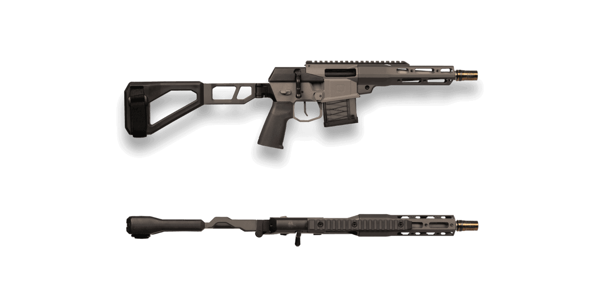
Q LLC
Q Mini Fix 300 BLK Pistol
1 shared compatibility tags
Marlin
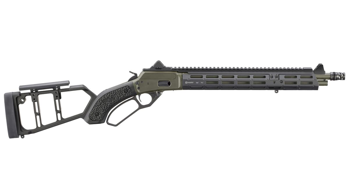
Marlin Mad Pig Customs Model 1894
1 shared compatibility tags
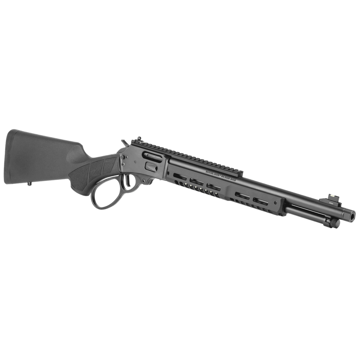
Smith & Wesson
Smith & Wesson Model 1854 Stealth Hunter
1 shared compatibility tags
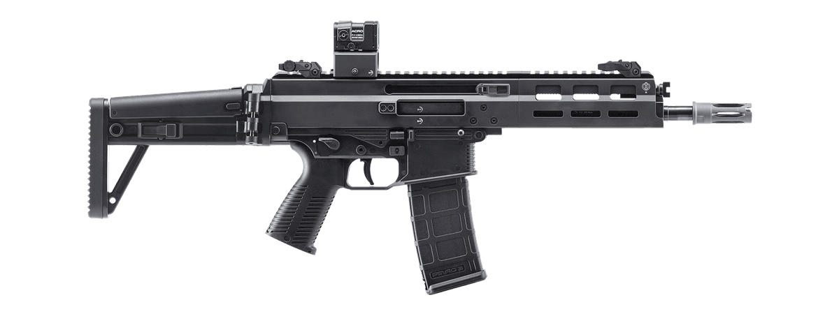
B&T
B&T APC223 PRO 420 mm
1 shared compatibility tags
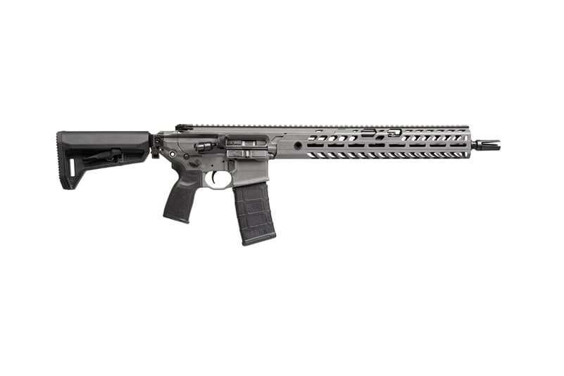
Sig Sauer
Sig MCX Virtus Patrol 16"
1 shared compatibility tags
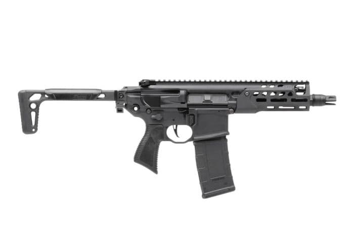
Sig Sauer
Sig MCX Rattler LT 6.75"
1 shared compatibility tags
Similar Products
Compatible Platforms
+303 more

Compatibility Tags
Build Your Custom Configuration
Add the Steiner DBAL-A3 to your build and see how it enhances your platform.